Close Menu

    Subscribe to Updates

    Get the latest creative news from FooBar about art, design and business.

    What's Hot

    AMTS 2026 to Open in Shanghai as World’s Largest Automotive Manufacturing Engineering Show

    July 2, 2026

    People and Process at the Core GROB India Manufactures Its First India Made Machine

    July 1, 2026

    Maintenance & Rejuvenation of Spindles Restoring the Heart of Machine Tool Performance

    July 1, 2026
    Facebook X (Twitter) Instagram
    • About Us
    • Contact US
    • Advertise
    • Subscribe Magazine
    Publications Media Kit
    Facebook Instagram YouTube LinkedIn WhatsApp X (Twitter)
    Machine Tools World | Machine Tools Industry News | CNC Machine Manufacturers | Indian Manufacturing MagazineMachine Tools World | Machine Tools Industry News | CNC Machine Manufacturers | Indian Manufacturing Magazine
    Takasu
    • HOME
    • NEWS
      • Global Market
      • Latest News
      • Product Updates
    • MACHINING
      • CNC Machines
      • Cutting Tools
      • Metal Cutting
      • Metal Forming
      • EDM
      • Grinding
      • Die & Mould
      • Metalworking Fluids
    • AUTOMATION
      • Smart Automation
      • CAD/CAM
      • Machine Safety
    • METROLOGY
      • Metrology
      • Inspection Systems
      • Quality Control
    • INSIGHTS
      • People in Focus
      • Case Studies
      • Opinion
      • Company Profiles
      • Tech Innovations
      • Blogs
    • EVENTS
      • Event Coverage
      • Webinars
    • DIGITAL MAGAZINE
    Machine Tools World | Machine Tools Industry News | CNC Machine Manufacturers | Indian Manufacturing MagazineMachine Tools World | Machine Tools Industry News | CNC Machine Manufacturers | Indian Manufacturing Magazine
    Home - CAD/CAM - Wireframes, Surfaces, and Solids – What Are They?
    CAD/CAM

    Wireframes, Surfaces, and Solids – What Are They?

    MTW Editorial TeamBy MTW Editorial TeamJanuary 17, 2024Updated:June 17, 2026No Comments12 Views
    Facebook Twitter Pinterest LinkedIn WhatsApp Reddit Tumblr Email
    Wireframes, Surfaces, and Solids – What Are They
    Share
    Facebook Twitter LinkedIn Pinterest Email

    In most cases – and especially when a customer has provided only a description or 2D drawing of a part – the first step in the machining process is to build a digital model of the desired part. This model will be a precise, virtual 3D representation of the part’s dimensions, planes, and contours. In CAD (computer-aided design) programming, there are three main types of models: wireframe, surface, and solid. Each has its own strengths and weaknesses. Follow along as this blog describes what wireframe, surface, and solid models are as well as how to use them.

    Wireframes, Surfaces, and Solids – What Are They

    What are Wireframe models?

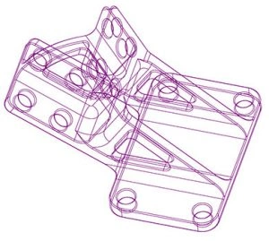
    Wireframe models are the oldest of the three listed technologies, but they are by no means outdated. Often the very first model of any machinable part will be created in wireframe. A wireframe model is a digital representation of a 3D object, but only at its edges – specifically, where two contiguous but distinct planes meet. These edges are demarcated by a line as if the design were a metal wire model of the part. Picture the way you would draw a see-through cube. That’s a wireframe model.

    The advantage of starting with a wireframe model is that you can accurately and precisely calculate the underlying structure of a part. Within the Mastercam interface, all wireframe models can be rotated, shrunk, enlarged, and edited with simple mouse-clicks. Wireframe models are exceptionally powerful in highly specific uses of tool control.

    What are Surface models?

    Next in the lineup is surface modelling: more exhaustive than wireframe but slightly more simple than solid modelling. Surface models, unlike wireframes, represents the part’s “skin”. If you spray painted an object and all its cavities, holes, and depressions, the paint would represent the surfaces that cover all the features of the part. However, this model wouldn’t include information about volume, thickness, or how each spray-painted element relates to each other. It is essentially a hollow shell representing the part.Wireframes, Surfaces, and Solids – What Are They

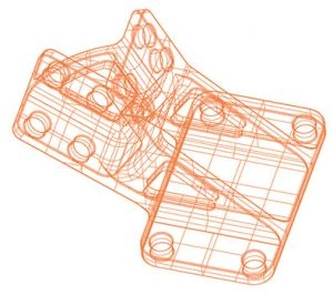
    This gives the user an advantage when the external shape needs to be adjusted in a way that would be impossible with a complete solid model. For example, if a part needs its faces built out one by one, surface modelling is the perfect solution because there need not be any other geometry attached to a face. If you were to try doing that with a solid model, you would have to build out multiple faces at once. Surface modelling would give you much more freedom as far as contour and direction. While it is possible to build a complete model using only surface modelling techniques, CAM programming usually relies on a combination with solid modelling. Due to the math behind their construction, there are also some highly complex shapes that are most easily modeled as a surface.

    What are Solid models?

    While wireframe and surface models show specific sections of a part, solid models are basically exact replicas of the part in a digital space. This means that its internal features and exact face thicknesses are rendered precisely within the model, as well as the edges and surfaces. A solid model of an automotive motor could be sliced to show detailed cross-sections at any angle. Since solids represent a full 3D version of a part, individual features can be moved, changed, duplicated, or deleted, and the impacted areas will change as well without the need to individually model each section as you would with surfaces.Wireframes, Surfaces, and Solids – What Are They

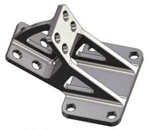
    How are Wireframes, Surfaces, and Solids combined?

    Most surface and solid models generally start with some wireframe entity. This first model gives the programmer the advantage of truly understanding the underlying framework of a part. Often, this view will give them the first idea as to how the part will be machined. Note, however, that some solid models will have no wireframe if they are saved off as a “brick.” This will not make the part unmachinable or the model uneditable, though.

    From the wireframe model, the subsequent surface or solid model can be built. In cases where some of the design is expressed as a surface model and some is expressed as a solid model, Mastercam allows users to select the two together and machine them as a single unit.

    Try it yourself!

    The best part of all? You can play with wireframe, surface, and solid modelling techniques in full functionality from the comfort of your own home. And it’s free. Download the free Mastercam Learning Edition today to experiment with Wireframe, Surfaces, and Solid Modelling.

    Wireframes, Surfaces, and Solids – What Are They


    For more information,
    www.mastercam.com

    Post Views: 523
    CAD CAM Industry Computer Aided Manufacturing Machining Processes Mastercam India Pvt Ltd
    Share. Facebook Twitter Pinterest LinkedIn Tumblr Telegram Email
    MTW Editorial Team

      Related Posts

      Workholding Devices and Productivity

      June 30, 2026

      When Microns Matter Laser Micromachining in Medtech

      June 30, 2026

      Air Turbine Tools Faster Finishes, Smarter Spindles Unlocking the Full Potential of Five-Axis Machining with High-Speed Spindles

      May 29, 2026
      Leave A Reply Cancel Reply

      Top Posts

      Machine Tools World August 2025

      August 25, 20252,468

      3D Printing: India’s Next Manufacturing Frontier

      June 14, 2025142

      Vertical and Horizontal Milling Machines: Key Points of Difference

      August 7, 2021190

      Gravity Die Casting and the Importance of Die Coats

      June 29, 202397
      Don't Miss
      Event Coverage

       B2B World Summit & Awards 2026 in Pune

      By MTW Editorial TeamJune 19, 20266

      Artificial intelligence has swiftly progressed beyond pilot projects and proof-of-concept discussions. AI-led go-to-market strategies, revenue…

      LIVE from INTEC 2026 | CODISSIA, Coimbatore

      June 19, 2026

      GMT Engineers Showcases Advanced Laser Cutting Solutions for Smart Manufacturing

      June 15, 2026

      FFG Showcases Advanced CNC Machining Solutions for the Next Generationof Manufacturing

      June 13, 2026
      Stay In Touch
      • Facebook
      • Twitter
      • Pinterest
      • Instagram
      • YouTube
      • Vimeo

      Subscribe to Updates

      Get the latest creative news from SmartMag about art & design.

      About Us
      About Us

      MACHINE TOOLS WORLD magazine is a monthly machine tool industry magazine in India since from last 10 years, catering to Indian & global machine tools, CNC machine manufacturers, Cutting tools, Metal Forming Machine Manufacturers, CAD-CAM, Metrology, Lubricant, Grinding Machine Players.

      Facebook X (Twitter) Instagram YouTube LinkedIn WhatsApp
      Our Picks

      AMTS 2026 to Open in Shanghai as World’s Largest Automotive Manufacturing Engineering Show

      July 2, 2026

      Cutting Tool Industry Keeps in Step with Technological Advancements Worldwide

      June 30, 2026

      B2B World Summit Pune 2026 Explores the New Formula for Enterprise Growth

      June 25, 2026

      Subscribe to Updates

      Get the latest news, product insights, and expert opinions from the world of machine tools and manufacturing, delivered straight to your inbox.

      © 2026 MachineToolsWorld.
      • Terms & Conditions
      • Privacy Policy
      • Disclaimer Policy

      Type above and press Enter to search. Press Esc to cancel.

      Prisma Banner